Skip to content
  • Blog
  • Categories
  • Recent
  • Tags
  • Popular
  • Users
  • Groups
Skins
  • Light
  • Brite
  • Cerulean
  • Cosmo
  • Flatly
  • Journal
  • Litera
  • Lumen
  • Lux
  • Materia
  • Minty
  • Morph
  • Pulse
  • Sandstone
  • Simplex
  • Sketchy
  • Spacelab
  • United
  • Yeti
  • Zephyr
  • Dark
  • Cyborg
  • Darkly
  • Quartz
  • Slate
  • Solar
  • Superhero
  • Vapor

  • Default (No Skin)
  • No Skin
Collapse
Brand Logo

Community Forum

  1. Home
  2. Categories
  3. MAX31865 PT100 and PT1000
  4. PT100 and PT1000 Breakout Board with MAX31865

PT100 and PT1000 Breakout Board with MAX31865

Scheduled Pinned Locked Moved MAX31865 PT100 and PT1000
pt100max31865arduinopt1000rtd
28 Posts 10 Posters 22.5k Views 1 Watching
  • Oldest to Newest
  • Newest to Oldest
  • Most Votes
Reply
  • Reply as topic
Log in to reply
This topic has been deleted. Only users with topic management privileges can see it.
  • B Offline
    B Offline
    BlackBrix
    wrote on last edited by
    #9

    Hi,
    I just found this project on tindie and I think I should order some ...
    from the arduino library I can see that it is maybe only supporting temperatures grater than 0°C (?) in an exact way ?
    (cause the RTD_C constant is not used ?)
    It would be great to fix this (or maybe I can extend the library myself) for temperatures below 0°C
    The formulas are quite simple, I found them here --> https://24max.de/elektronik/Pt100-Formulas.pdf

    1 Reply Last reply
    • CharlesC Offline
      CharlesC Offline
      Charles
      wrote on last edited by
      #10

      @BlackBrix
      What to you mean by greater from 0°C, it works fine on my tests

      But may be you meant lower than 0°C ? To be honest I didn't tested that one, I need to check, but I think it should works

      1 Reply Last reply
      • G Offline
        G Offline
        gruenst
        wrote on last edited by
        #11

        Hi Charles,
        I tried your breakout board with the same setup I used for mine, and it works. So it's not the software, and not the Arduino Feather board. Must be the difference in setup of the breakout board.

        I solved an issue with the ground pin, so DVDD and VDD now both show 3.3V.
        Further, I connected Force2 with Force+ instead of Ground (different to the diagram above), to adapt it to yours. Which doesn't change anything. It shouldn't be the difference in packaging, as SSOP takes less power than your TQFN. So the only difference I see are the two ferrite beads, which I don't use.
        Which ones do you use? Or would you see a mistake I made with the assembly shown above?

        Thanks!
        Stefan

        1 Reply Last reply
        • CharlesC Offline
          CharlesC Offline
          Charles
          wrote on last edited by
          #12

          @gruenst
          the ferrite board (470 Ohm) are used to do

          • FB1 Filtering AVDD
          • FB2 Filtering AGND

          But you can bypass them, ie put a wire instead, should also work

          1 Reply Last reply
          • F Offline
            F Offline
            Fernando Vinícius G. Magro
            wrote on last edited by
            #13

            Hi CHARLES,
            Can you give me information (specs) about the SMD FB1 and FB2 ?
            There is a Mouser or Digikey part number for this item?
            Thanks

            1 Reply Last reply
            • CharlesC Offline
              CharlesC Offline
              Charles
              wrote on last edited by
              #14

              @Fernando-Vinícius-G-Magro
              the Mouser link was in my previous response but it's a 470 Ohm classic Ferrite Board
              http://eu.mouser.com/Search/ProductDetail.aspx?R=BLM18PG471SN1Dvirtualkey64800000virtualkey81-BLM18PG471SN1D

              1 Reply Last reply
              • CharlesC Charles

                Today I would like to introduce a new breakout board to read temperature values from the most used sensors in the industry such as PT100 and PT1000 (well at least in France). Why this board ? It’s not the first… Continue Reading

                Click here to see the full blog post

                E Offline
                E Offline
                Erik van Os
                wrote on last edited by
                #15

                @Charles
                Hi charles,
                have a question about your nice project, can I use it also for a Raspberry PI 3B?
                thanks Erik van Os

                1 Reply Last reply
                • CharlesC Offline
                  CharlesC Offline
                  Charles
                  wrote on last edited by
                  #16

                  @Erik-van-Os
                  thanks, yes for sure you can use it with RPI3 but you'll need to adapt the code, may be using WiringPi library.

                  1 Reply Last reply
                  • R Offline
                    R Offline
                    Roelof Loots
                    wrote on last edited by
                    #17

                    Hi Charles, would it be possible to connect more than one of these boards to a single arduino uno somehow? I just bought 3, and would just like to know if it would be possible to read temperatures from 3 x RTD's

                    1 Reply Last reply
                    • CharlesC Offline
                      CharlesC Offline
                      Charles
                      wrote on last edited by
                      #18

                      @Roelof-Loots
                      Yes it's possible, each RTD board just need to have it own chip select pin (and led pin if you use it) all SPI pins can be shared (MOSI, MISO, SCLK), that the goal of SPI 😉

                      Take care your Arduino MUST be only 3V3 because RTD boards are 3V3 only, if your arduino is 5V you need level shifter and with 3 RTD boards it will be a real pain....

                      R 1 Reply Last reply
                      • CharlesC Charles

                        @Roelof-Loots
                        Yes it's possible, each RTD board just need to have it own chip select pin (and led pin if you use it) all SPI pins can be shared (MOSI, MISO, SCLK), that the goal of SPI 😉

                        Take care your Arduino MUST be only 3V3 because RTD boards are 3V3 only, if your arduino is 5V you need level shifter and with 3 RTD boards it will be a real pain....

                        R Offline
                        R Offline
                        Roelof Loots
                        wrote on last edited by
                        #19

                        @Charles - Thx for that...im using a arduino uno, and looks like its got 3V3, so I should be able to do it correctly using a breadboard, else ill just get logic level converters.

                        1 Reply Last reply
                        • CharlesC Offline
                          CharlesC Offline
                          Charles
                          wrote on last edited by
                          #20

                          @Roelof-Loots
                          Take care, even if your Arduino Uno has a 3.3V pin available (fine to power RTD), all I/O need also to be full 3.3V (MOSI/MISO/CS/CLK) which may not the case. IT's better to have a full 3V3 Arduino (even at 8MHz)

                          I'm using this one that have a switch to pass full board to 5V or 3V3 https://www.seeedstudio.com/Seeeduino-V4.2-p-2517.html or just find on ebay Arduino Pro Mini 3.3V USB 😉

                          1 Reply Last reply
                          • V Offline
                            V Offline
                            Vishi100
                            wrote on last edited by
                            #21

                            Hi! I'm trying to interface MAX31865 (PT1000) to STM32F334 controller (Nucleo64) (Cortex M4) board. I used the Arduino codes from github and coded the STM32F3 controller. Both the sensor and the controller are tested & working fine. But when i read from MAX31865, I'm getting the maximum values in all the registers. Can i get plz get some help as to what might have gone wrong??

                            1 Reply Last reply
                            • F Offline
                              F Offline
                              Fernando Vinícius G. Magro
                              wrote on last edited by
                              #22

                              Hi Charles, the IRQ (DRDY pin) of Max31865 need to be wired?
                              I can presume that it can be useful to trigger an interrupt when a conversion is completed, but it is not mandatory. Can i left it unconnected ?

                              1 Reply Last reply
                              • CharlesC Offline
                                CharlesC Offline
                                Charles
                                wrote on last edited by
                                #23

                                @Fernando-Vinícius-G-Magro
                                The IRQ line should be wired only if you need an interrupt. So it's not mandatory don't worry you can left it unconnected.

                                1 Reply Last reply
                                • R Offline
                                  R Offline
                                  Rolando
                                  wrote on last edited by
                                  #24

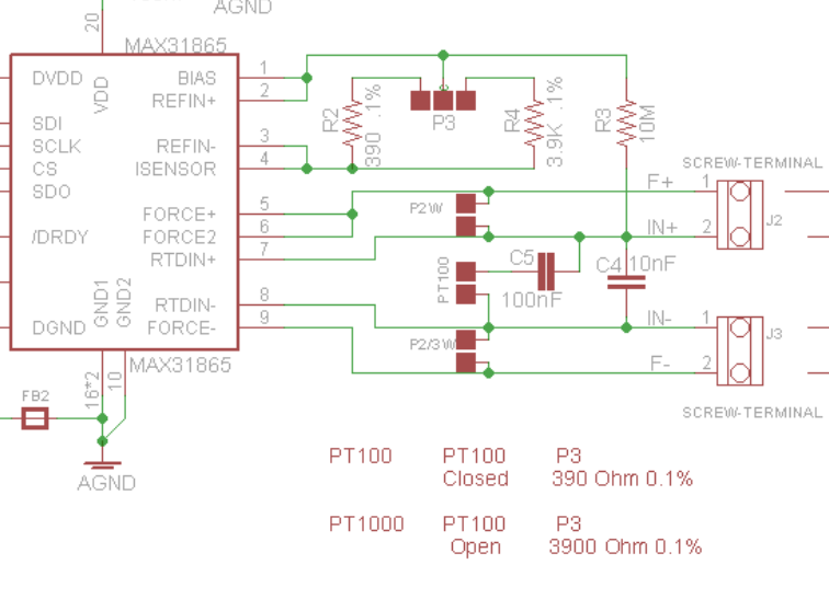
                                  Hi Charles, what function R3 is supposed to do? And why 390Ω instead of 400Ω as recommended on Maxim datasheet? Thank you in advance.

                                  CharlesC 1 Reply Last reply
                                  • R Rolando

                                    Hi Charles, what function R3 is supposed to do? And why 390Ω instead of 400Ω as recommended on Maxim datasheet? Thank you in advance.

                                    CharlesC Offline
                                    CharlesC Offline
                                    Charles
                                    wrote on last edited by
                                    #25

                                    @rolando do you mean R2?

                                    you use R2 for PT100 (R4 unsuded) and R4 for PT1000 (R2 unused)

                                    it's 390 and 3.9K because sourcing was easier with these values

                                    0_1534866170814_356df6bc-9fb8-46a9-842b-9e66e505bbc1-image.png

                                    It's no problem, it's adjusted to correct valuee into the code look for an example here

                                    1 Reply Last reply
                                    • C Offline
                                      C Offline
                                      cbparks
                                      wrote on last edited by
                                      #26

                                      Thank you for the very fine design. Would you please mind helping with the sketch changes to read temperature in fahrenheit? Thank you.

                                      1 Reply Last reply
                                      • C Offline
                                        C Offline
                                        cbparks
                                        wrote on last edited by
                                        #27

                                        Figured out the fahrenheit question but with a PT100 the ohms do not read correctly. Changed all the rtd.raw_resistance to rtd.resistance. That corrects the correct ohms reading in the serial monitor but not on the oled display. Appreciate any suggestions on how to correct. thank you.

                                        1 Reply Last reply
                                        • adminA Offline
                                          adminA Offline
                                          admin
                                          wrote on last edited by admin
                                          #28

                                          @cbparks
                                          The reading and display depends on reference resistors soldered on your boards, in my design it's 390 for PT100 and 3900 for PT100, it's declared here and the only place it should be

                                          Then declare if you want to use PT100 or PT1000 here

                                          1 Reply Last reply

                                          Hello! It looks like you're interested in this conversation, but you don't have an account yet.

                                          Getting fed up of having to scroll through the same posts each visit? When you register for an account, you'll always come back to exactly where you were before, and choose to be notified of new replies (either via email, or push notification). You'll also be able to save bookmarks and upvote posts to show your appreciation to other community members.

                                          With your input, this post could be even better 💗

                                          Register Login
                                          Reply
                                          • Reply as topic
                                          Log in to reply
                                          • Oldest to Newest
                                          • Newest to Oldest
                                          • Most Votes


                                          2

                                          Online

                                          5.8k

                                          Users

                                          565

                                          Topics

                                          5.3k

                                          Posts

                                          Top Topics

                                          Popular Tags

                                          teleinfo
                                          25 topics
                                          arduino
                                          19 topics
                                          remora
                                          16 topics
                                          esp8266
                                          10 topics
                                          arduipi
                                          10 topics
                                          raspberry
                                          8 topics
                                          wifinfo
                                          7 topics
                                          broadcast
                                          7 topics
                                          Copyright © 2022 Charles-Henri Hallard | Return to blog page | Powered by NodeBB
                                          • Login

                                          • Don't have an account? Register

                                          • Login or register to search.
                                          • First post
                                            Last post
                                          0
                                          • Blog
                                          • Categories
                                          • Recent
                                          • Tags
                                          • Popular
                                          • Users
                                          • Groups